Multi-Purpose Transfer System (MPTS)
A mechanical prefab panel flipping mechanism designed for manufacturing and assembly applications.
About This Project
In my final year of my BSc. in Mechanical Engineering, I took my capstone course which involved undertaking the design of a project in a team of 6. My team, named Flip Side Engineering, was contracted to design a Multi-Purpose Transfer System (MPTS) to flip and orient prefabricated concrete panels at any angle. We considered three concepts based on different flipping mechanisms and ultimately decided on proceeding with the passing forks which is presented here.
Background
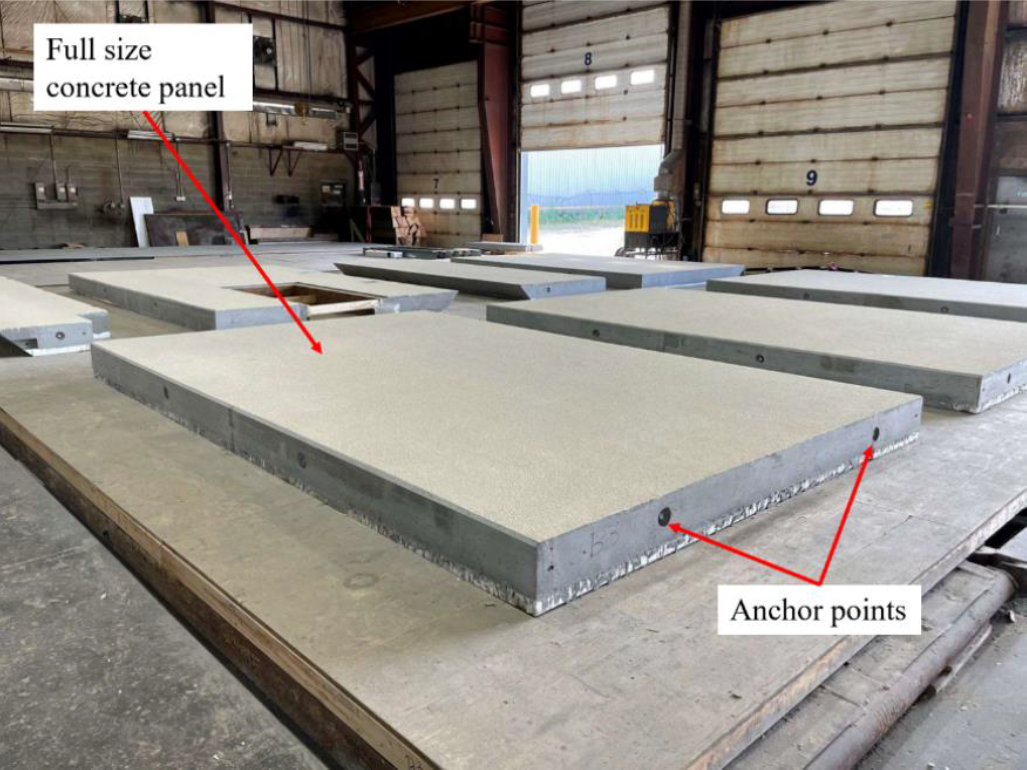
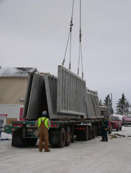
Prefabricated and modular concrete construction panels have become increasingly common in the construction industry. The walls, floors and ceilings of a building can be prefabricated in a factory, then transported to a jobsite where they are assembled. Handling finished panels requires the use of embedded anchors which are only designed for one to two uses. Currently, overhead cranes lift the panels by these anchors. Using the cranes creates a bottleneck in production since they are needed in multiple stages of panel construction.
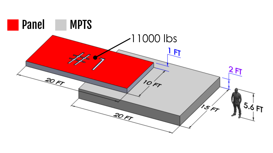
To solve this, my team was tasked with designing a Multi-Purpose Transfer System (MPTS) that can orient concrete panels so they can be worked on and received at any angle without the use of overhead cranes. The MPTS should be able to accept varying sizes of timber and steel building frames as well as accommodate potential doorways and windows.
To summarize the project criteria, the final design should be:
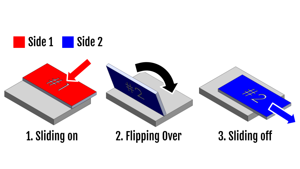
- able to flip and hold panels between 0° and 180° relative to the ground
- able to slide the panel off at any angle
- under the budget of $150,000 CAD
- operable by a single person
- able to flip various panels within a 15 ft width
Concept Refinement
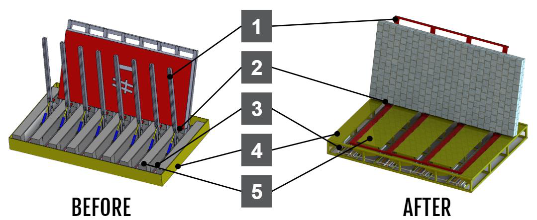
From our initial design in the middle of the term, notable improvements had to be made to the mechanical design. The preliminary concept achieved the same functionality as the final design; however, it had many unrefined parts and oversimplified assemblies. These differences can be seen in the figure below and explained in the table after that.
| Number | Before | After | Description |
|---|---|---|---|
| 1 | 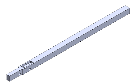 | 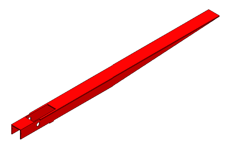 | Fork Design: Previously, 8 forks were used on each side of the device resulting in a total of 16 hydraulic cylinders. This was meant to compensate for the smallest panel size. After clarification with the client, the smallest panels would be oriented along their longest edges, increasing the minimum span between forks. As a result, the spacing between forks was increased and the number of forks on each side was reduced to 4. The ends of the forks were also tapered to reduce the overall weight. |
| 2 | 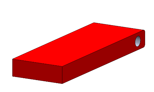 |  | Heel Block Mechanism: Hydraulic cylinders were incorporated to enable remote activation of the heel block. Previously, the heel block required manual activation, which was inconvenient for the workers and slowed the flipping procedure. |
| 3 | N/A | 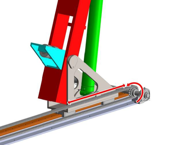 | Chain and Sprocket Mechanism: Leadscrews were replaced by a chain and sprocket mechanism to power the linear motion of the forks. The chain and sprocket mechanism is less expensive and easier to align than leadscrews. The amount of force required to translate the heaviest panel was deemed small enough that leadscrews were not required. |
| 4 | Table and Frame: The frame was refined to provide effective support for the panel and storage of the forks and linear rails. | ||
| 5 | UHMW Plastic Pads: A layer of UHMW plastic was added to the surface of the table to help the panel slide on and off with less friction. UHMW plastic also provides slight cushioning to prevent damage to the panels.. |
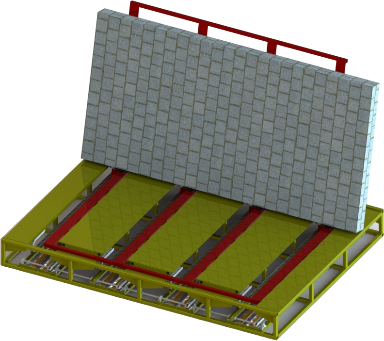
Final Design Overview
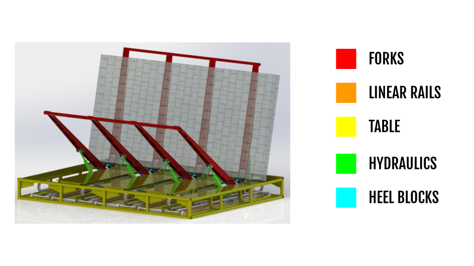
The main goal of the MPTS is to flip and orient prefabricated construction panels to allow workers to prepare them for final transport. It must be able to flip panels up to 20 feet long and 10 feet wide and must fit inside a 20-foot by 15-foot area. The MPTS consists of two opposing sets of 4 forks integrated into a table as seen below. All motion is powered by a hydraulic power unit and control system supplied by the client. The MPTS is designed for use with hydraulic components that operate at a working pressure of 3000 psi. This operating pressure was chosen due to the availability of higher-quality components that operate at this pressure.
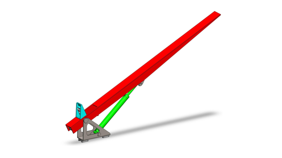
Forks
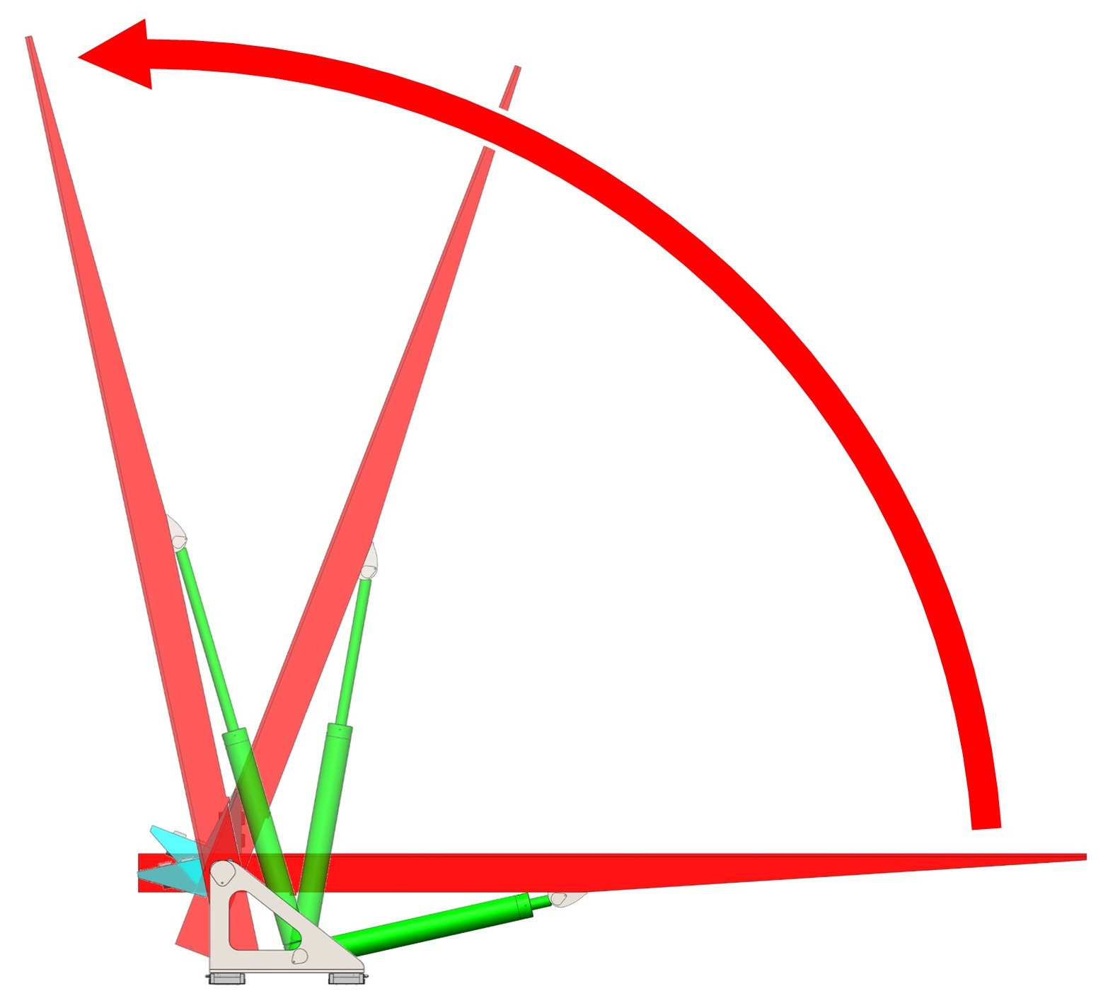
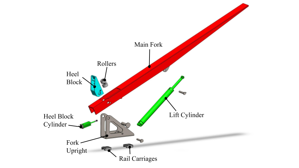
The forks’ main function is to lift, flip, and translate panels. The fork subassembly consists of a main fork to support and lift the panel, a retractable heel block in the main fork, and an upright to support the fork and mount the lift cylinder. The base, heel block, and main fork are all weldments made from 44W steel plate. This material selection is supported by 44W steel being sufficiently strong in addition to being less expensive, readily available, and easier to weld compared to higher carbon steels. Both sets of forks in the MPTS are capable of rotating 110º relative to the ground to aid the panel transfer from one set of forks to the other.
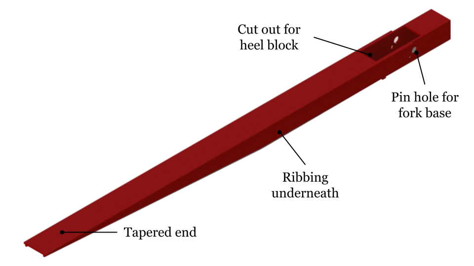
The main fork supports the panel while it its being lifted and translated. It is pinned to the fork base at one end and the main hydraulic cylinder is pinned near the middle of the fork. The main fork is tapered near the end to reduce weight and material used as shown in Figure 8, and ribs are welded to the underside to increase its rigidity. Each set of forks is joined with a brace at the tips to keep them timed when not under load, as small differences in friction within each fork assembly may cause them to desynchronize when not supporting the load of a panel. The end of the main fork contains a retractable heel block.
The fork upright supports the main fork and the large hydraulic cylinder that powers the lifting motion. The lift cylinders have a bore of 3.5” and can exert up to 28800 lbs of force at 3000 psi. The entire fork assembly is translated on linear rails with carriages bolted to the fork upright. This fork assembly is an innovative and efficient method to flip and transfer panels in a safe manner.
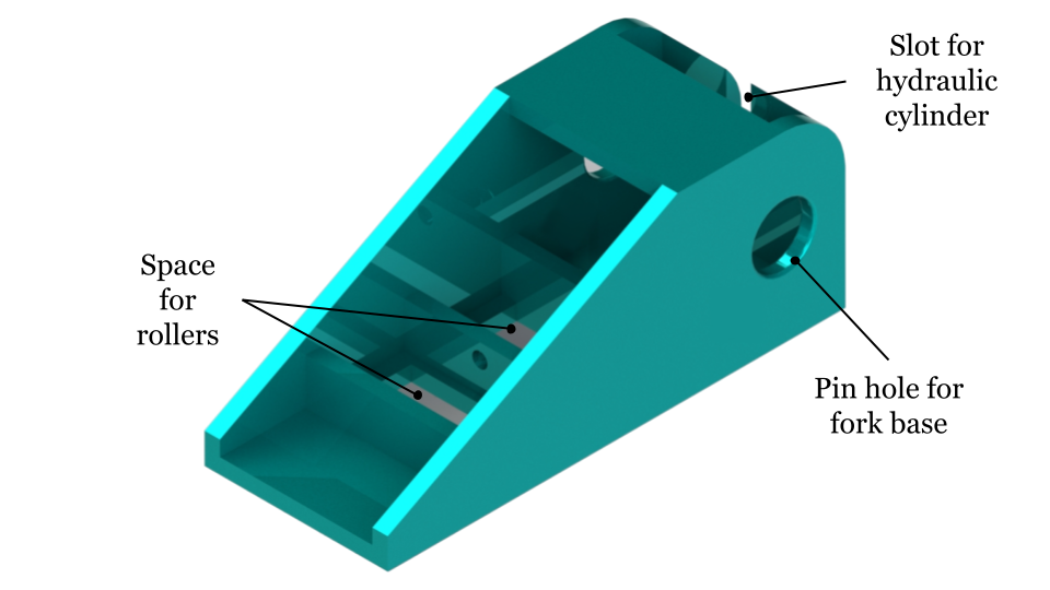
Heel Blocks
I worked on the entire heel block assembly. The heel block’s main function is to support the panel while the forks lift, translate, and transfer the panels in a safe manner. Each heel block incorporates rollers so that the panel can more easily slide off the device. When not in use, the heel block retracts into the main fork to prevent it from interfering with the panel being slid onto the device. The heel block is engaged and retracted by a small hydraulic cylinder with a range of motion of 90°. I went through many iterations of the design to ensure the hydraulic cylinder did not get in the way of the heel block motion. The retractability of the heel block made designing this component a challenge due to its small footprint.
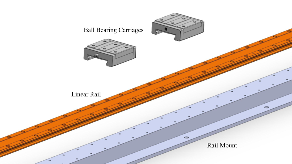
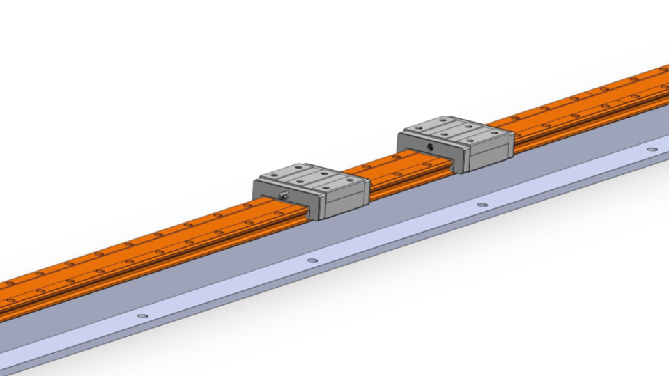
Linear Rails
The purpose of the linear rail subassembly is to translate the forks so that panels may be transferred from one set of forks to the other during the flipping process. Each individual fork in both sets requires its own rail: due to space constraints, opposing forks must be able to slide past one another, making it impractical for forks to share a rail. The rails are rated to support the large loads created by the cantilever arrangement of the fork when the panel is laying flat. They can also support up to 13 kN·m of rolling moment, required for when the panels are slid off the end of the device. Each rail is mounted to a rigid rail carrier weldment that is anchored to the floor and bolted to the frame of the MPTS to keep it aligned. Each fork assembly slides along its rail on ball bearing carriages. Two carriages are bolted to each fork upright, with one positioned at each end.
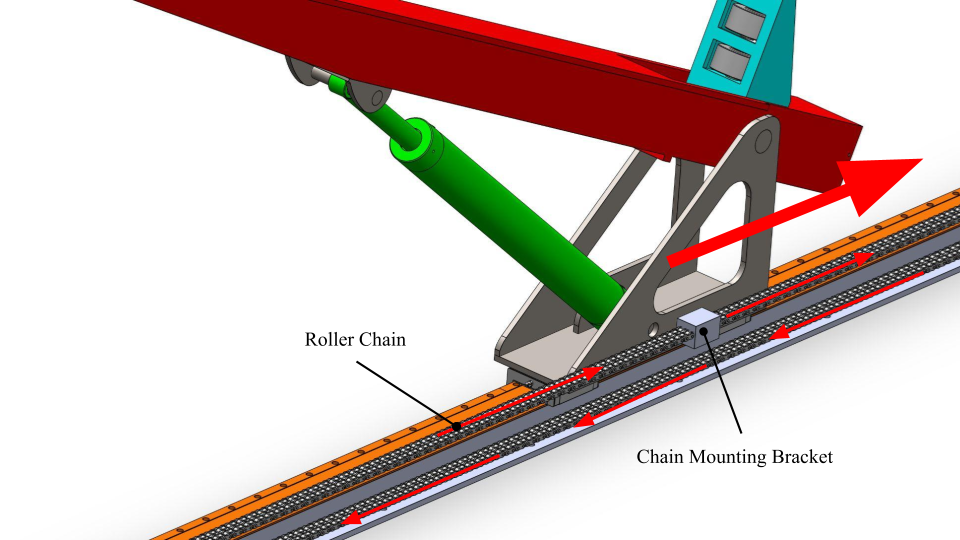
The forks are moved along the rail by a chain and sprocket mechanism that is powered by a hydraulic motor. The chain is connected to the fork upright with a bracket that can be adjusted to tension the chain and adjust the relative position of the fork assembly as shown below.
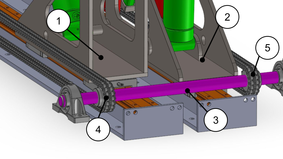
Because the chain is tensioned at the fork base bracket rather than by positioning the sprocket, the device only requires two shafts to independently power the motion of both opposing sets of forks. Each shaft will have eight sprockets mounted to it: four of them will be keyed to the shaft to drive the translational motion of one set of forks, and the other four will spin freely on bearings as idlers to allow the opposing set of forks to translate independently. This arrangement is shown below. The fork assembly (1) is driven by the sprocket (4) that is keyed to the shaft (3). The fork assembly (2) is driven by a sprocket keyed to the opposing shaft, and sprocket (5) rotates freely on the shaft.
A chain was chosen for this application due to simplicity and greater tolerance for misalignment over a leadscrew. While not as robust as a ball screw or leadscrew, a chain was deemed sufficient for this application due to the coefficient of friction of the linear rails falling in the range 0.01 to 0.05, meaning that a chain would not see excessive wear. The motor powering the chain and sprocket mechanism can supply 5991 in·lb of torque at 3000 psi.
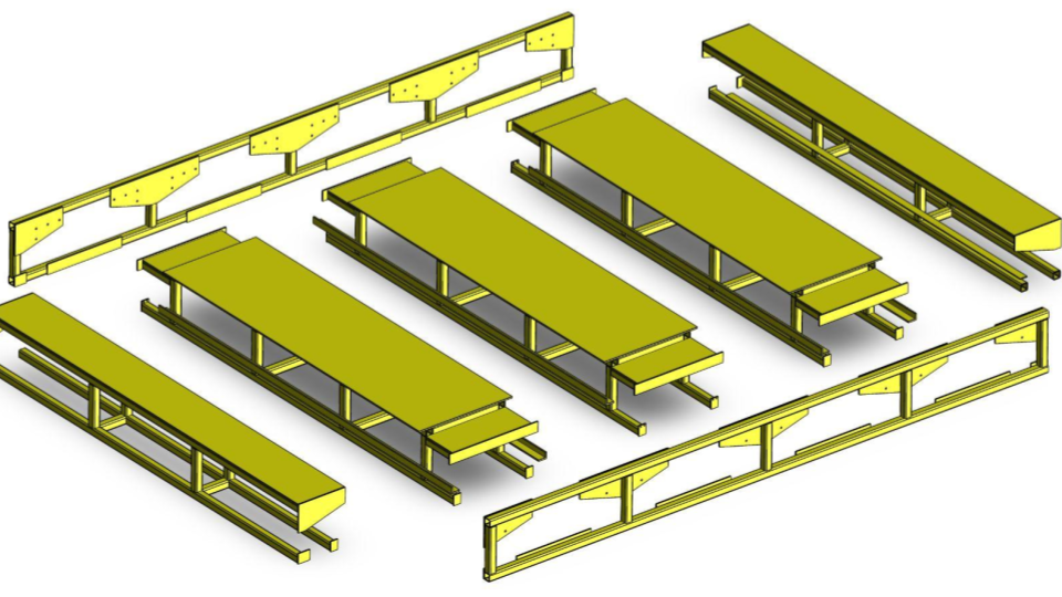
Transfer Table
The frame of the MPTS incorporates a transfer table that supports the panel when it is laying flat or being loaded onto the device. The table surface is made of 44W steel plate, and the table frame consists of rectangular structural steel tube. For ease of assembly, the frame consists of five table section weldments that are bolted to two side weldments. To efficiently slide the panel on and off the MPTS, pads made from UHMW plastic were added to the table’s surface. Some advantages offered by this material are its durability and reduced friction. When not in use, the forks are effectively stored within the width of the table and sit at the same height as the table surface. As stated by the client, the MPTS must be a compact and storage friendly design. All components fit neatly within the space enclosed by the table structure. The middle table sections have enough room to house a low-profile hydraulic power unit if desired by the client.
Motion Sequence